


Last year I had the chance to get a beautiful Pilot TV-37. This little wonder has the outer appearance of a radio, with a small 3 inches round screen.
It was made in 1948, marketed as a portable TV and sold at $99 so it has the merit of being the first commercial TV with a cost below $100.
It features an electrostatic CRT type 3KP4, of 3 inches. Today this is by far the most difficult part to replace of the set, as electrostatic CRTs with P4, unlike their oscilloscope cousins which used P1, were never produced in great quantities. Thankfully, the 3KP4 that came with my set is in great shape. Anyway, just in case, the first thing I did when I bought this set, was to also get a 3KP1, so I could use that one during the restoration to avoid any damage to the 3KP4.
As for the restoration, I will only deal with the specifics of my case, because in Internet there are 2 excellent step by step pages that deal with the subject:
- http://antiqueradio.org/PilotTV-37.htm
- http://www.electronixandmore.com/televisions/pilot/index.html
- http://www.mcclellans.com/PilotTV37Restoration.htm
Key notes of the process
Isolation:
First thing was to get a Variac transformer, and a 220V to 110V isolator transformer (In Argentina we use 220V). This is extremely important because this TV has not a power transformer, so the chassis is always tied to one of the mains line. And that is a call to electrocution. Also, the typical 220-110 transformer is an autotransformer that does not provide isolation. So I simply ordered an isolation transformer at a local shop.
CRT filament:
I removed the CRT filament from the filament string placing a 12 ohms 5W resistor in its place, and feed the 6.3V to the filament from a transformer, to avoid the CRT getting a high voltage during power up. The 3KP4 is worth its weight in gold, so I want to keep it as safe as possible.
Wax capacitors:
Next thing was obviously to recap the set, I used polyester film capacitors, mainly of 630volts, and the difficult part was to get the high voltage caps because here in Argentina they are rare. I ended up making combinations of 1600volts caps which was all what I could find in local stores. However this lead to other problems, so I decided to buy a lot of Russian capacitors at eBay.
Update: I received the Russian HV caps from Lithuania, they are GREAT!, they are really high quality and they are cheap! This solved all my linearity problems. The store is http://stores.shop.ebay.com/KW-TUBES and BTW the guy is a HAM too.
Electrolytic capacitors:
I replaced the electrolytic capacitors of B+ and B- with scrap caps from a PC power supply. These were 220uF rated at 200V. They may be too big, and put a heavy initial load to the rectifiers but, what the heck, those tubes are easy to replace, can even be easily replaced with Si diodes if needed, and a ripple was cut by a 10 fold. You have to consider that B+ and B- are both half wave rectified, and that usually means a big hum. To make things as nice as possible I later emptied the original can capacitors, and placed the new electrolytics inside the old cans, that was a dirty and time consuming task! BTW, the original caps were completely dry, so the moral of the story is... ALWAYS REPLACE ALL THE CAPS.
I also replaced the 3 low voltage electrolytic capacitors later because I was experiencing quite some trouble (I should have done so at once when I began):
- Audio detector
- Contrast: very important because otherwise the contrast will oscillate when high
- Synch separator: important because otherwise the horizontal hold will suck.
High voltage:
Getting high voltage was not easy, initially I could barely get between 1000 and 1400 volts from the oscillator (even after careful tweaking), and that wasn't enough to get something out of the CRT. By chance, I thought that I could place a ferrite stick inside the transformer air core. With that I could get it boosted to around 1800V, just enough to have a raster. If I could get perhaps 2000 to 2200, things would be a lot better, especially when using the 3KP1 which besides being green, it is dimmer. My tube tester tested the oscillator tube good for emission but anyway, I tried another tube, unfortunately with the same results. If somebody can give me a hand on getting a higher voltage, please email me, according to the schematics and notes, it should be near 2500V.
Video signal:
Initially I had no video at all, so after some analysis with the oscilloscope, I found that the video detector was not working and I was getting modulated IF signal instead of the video. By placing a germanium diode to the chassis I could confirm that I could get the video signal, and that the problem was the detector and not an earlier stage. I removed the shield, and I checked the 1N34 (which was amazingly old, I had never seen a diode in such a package, more or less like a ceramic fuse), and it was open. I simply replaced it with a Ge diode, and I immediately got in the oscilloscope a nice video signal. It was absolutely amazing that there was nothing to align in the oscillator, IF, etc even after 50 years of not being used, after replacing the diode it worked right away!
Sweep linearity:
I tuned the linearity to the best possible shape, but I had an awful raster, horrible non linear. The cause for this was that the high voltage capacitors I used to feed the deflection, particularly the vertical (low frequency), were of low capacitance, the schematics say 5nF but I could only get 500pF. I soldered a few extra ones in parallel to get at least 2nF, and the linearity was improved a lot. Getting high voltage capacitors in Argentina is not easy, so I have bought a lot of Russian capacitors at eBay, so I expect that once I replace them I will have a beautifully linear raster.
Update: I received the Russian HV caps from Lithuania, they solved all my linearity problems.
Sound:
So I had picture but yet no sound... I started tracing the issue, and soon found out that the sound IF transformer was open. This was the most difficult part, I had to carefully remove the shield, and then desolder the upper contacts without removing the whole transformer, next I unwound the top coils while counting the turns and taking notes on the direction, and finally I wound the 90 turns of the primary, and on top of that 8 turns for the secondary that is on top of it (which was originally fine, but I had to remove to get access to the primary). All this at 3AM, with some scrap wire I had from a very small power transformer. Then the miracle... a crystal clear sound came out of the speaker.
Brightness:
Brightness was quite dull, this was dramatically enhanced when I found that a resistor at the lower end of the brightness potentiometer had drifted up to twice its value.
Vertical distortion:
The image is distorted vertically, like with a half sine wave and also changed slightly its position as it seems the vertical synch from the TV signals is not synched with the mains as it should. I checked and the shifting matched exactly the ripple, so the issue seemed to be in the supply. When I placed both sweep signals (as they are BEFORE the sweep amplifiers) to the oscilloscope X and Y, I found a perfectly square raster, so the issue could be either at the amplifiers or the high voltage. After tracking with a high voltage probe, and the oscilloscope I found that the anode voltage had a ripple of nearly 150 volts, which was caused by a high ripple in the cathode (B-) of the oscillator tube. So, when the high voltage was lower, the electron beam has less speed, and that means more time for being deflected, thus wider image. When the voltage is high, that means less time, thus narrower image. I checked the schematic and found something very interesting, the cathode is getting B- from the first capacitor of the filter. I first tried to get the voltage from the second capacitor, but the 470 ohms resistor lowered the voltage too much, something that caused the high voltage to bee too low (near 1600V), and the CRT of course, too dim. What I did was to add a dedicated filter for this tube, with a 100 ohms resistor, and a 47uF second capacitor. This gave me nearly 1800V in the high voltage, which is jut enough to get a picture. I seriously need to find a way to increase the high voltage.
Current problems
- High voltage. I am currently getting about 1800V, when the specs mention 2500V. I have to figure out some way to get 400 or 500 volts extra.
- Retrace lines. These old sets don't have blanking during the retrace lines, this is noticeable during the vertical retrace, as you will see white diagonal lines, according to the contrast and brightness. I read somewhere in Internet, that by just placing a capacitor in the correct place, you can force the blanking, I guess I might try that at some point after everything else is sorted out, but really doesn't bother too much, with the correct settings at the brightness and contrast controls, you don't see them.
- I found in the schematics (and the TV) something that I don't understand. One of the plates of the vertical amplifier is getting its voltage from the bottom of the focus, I would have expected it to get from B+ like the horizontal circuit. I really have no clue of why is that. Can somebody enlighten me on this?
- A missing knob. One of those nice bakelite knobs with a ship wheel is missing, but buying one at ebay means spending more than 50 bucks! I guess I'll try to make a copy of it with resin, worst case I will simply throw $8 in resin to the garbage. I have to try.
- One rod from the bakelite front is broken and missing. When I bought it I knew that but I didn't know it was a whole piece, altogether. So I assumed I could simply replace it. Now, fixing that is more difficult, because I have to make a mold to fit in the right position in the front, and then fill it with resin... I really don't know if I even want to try that.
- I have to clean some parts which have too much white aluminum oxide, I should have done that first, but at the time I wanted to get into the electronics fast and see those tubes glow! Who cares the rust?!

Conclusion
Photos
Empty cabinet |
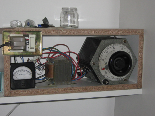
First things first Variac + isolator transformer to slowly power up |
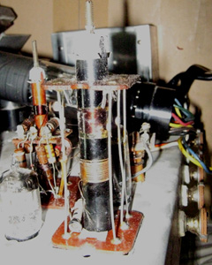
Sound IF transformer (front) and video detector transformer (behind the 6AL5 sound detector tube) |
AFTER - Chassis bottom with new capacitors (Notes: before replacing the HV with Russian caps) |
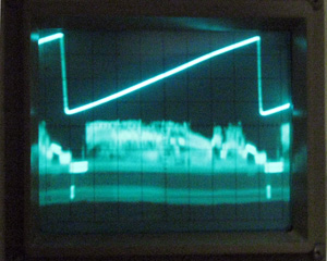
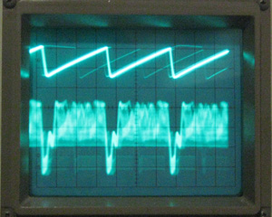
Vertical sawtooth versus video signal |
Horizontal sawtooth versus video signal |
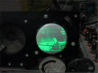
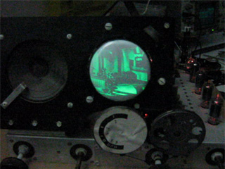
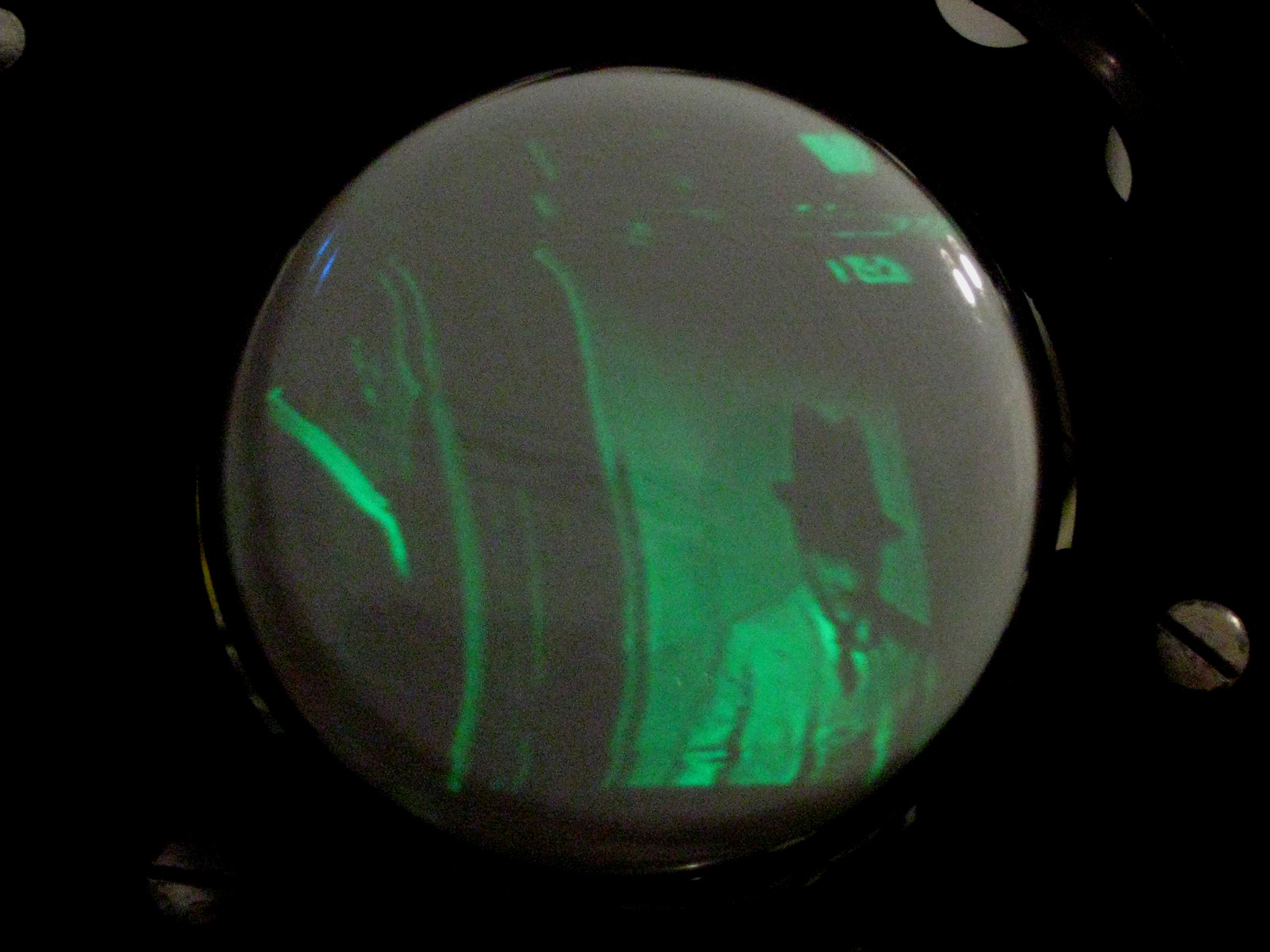
First movies in green :) | First movies in green :) |
Closer look of the green 3KP1 | |
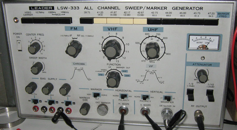
Leader LSW-333 Sweep and mark generator Used for calibration, it has many features. Unfortunately, due to the weird IF (25MHz instead of 45MHz) this receiver uses, I cannot perform visual alignment of IF with the LSW-333. |
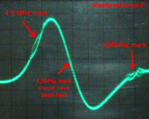
Sound IF response Note that the 4.5MHz marker should be in the middle of the waveform, so this is misaligned. |


| < Prev | Next > |
|---|

